STM32的PWM輸入模式設(shè)置并用DMA接收數(shù)據(jù)
參考 :STM32輸入捕獲模式設(shè)置并用DMA接收數(shù)據(jù)
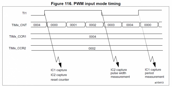
PWM input mode
This mode is a particular case of input capture mode.
本文引用地址:http://butianyuan.cn/article/201611/318023.htmThe procedure is the same except:
? Two ICx signals are mapped on the same TIx input.
? These 2 ICx signals are active on edges with opposite polarity.
? One of the two TIxFP signals is selected as trigger input and the slave mode controlleris configured in reset mode.
For example, you can measure the period (in TIMx_CCR1 register) and the duty cycle (inTIMx_CCR2 register)
of the PWM applied on TI1 using the following procedure (dependingon CK_INT frequency and prescaler value):
? Select the active input for TIMx_CCR1: write the CC1S bits to 01 in the TIMx_CCMR1register (TI1 selected).
? Select the active polarity for TI1FP1 (used both for capture in TIMx_CCR1 and counterclear): write the CC1P and CC1NP bits to ‘0’ (active on rising edge).
? Select the active input for TIMx_CCR2: write the CC2S bits to 10 in the TIMx_CCMR1register (TI1 selected).
? Select the active polarity for TI1FP2 (used for capture in TIMx_CCR2): write the CC2Pand CC2NP bits to ‘1’ (active on falling edge).
? Select the valid trigger input: write the TS bits to 101 in the TIMx_SMCR register(TI1FP1 selected).
? Configure the slave mode controller in reset mode: write the SMS bits to 100 in theTIMx_SMCR register.
? Enable the captures: write the CC1E and CC2E bits to ‘1’ in the TIMx_CCER register.

STM32的PWM輸入模式設(shè)置并用DMA接收數(shù)據(jù)
項目中需要進行紅外學(xué)習(xí),如果采用輸入捕獲的方式,因為定時器只能捕獲上升沿或者下降沿,
所以只能獲得周期,而不能得到具體的紅外波的高低電平的時間.
所以采用PWM輸入的方式進行捕獲.采用的是PA8腳,對應(yīng)TIM1的通道1.
/********************************************************************** 函數(shù)**********************************************************************//********************************************************************** 接口函數(shù):初始化紅外學(xué)習(xí)模塊**********************************************************************/void inf_infrared_study_init( void ){//初始化io口inf_init_io( );//初始化中斷//inf_init_irq();//初始化定時器inf_init_timer( );//打開DMAinf_infrared_study_open_dma( 1 );//打開定時器inf_infrared_study_open_timer( 1 );}/********************************************************************** 初始化io口**********************************************************************/static void inf_init_io( void ){//定義IO初始化結(jié)構(gòu)體GPIO_InitTypeDef GPIO_InitStructure;//初始化時鐘RCC_APB2PeriphClockCmd( RCC_APB2Periph_GPIOB, ENABLE );//管腳初始化 GPIO_InitStructure.GPIO_Pin = GPIO_Pin_8;//設(shè)置為輸入 GPIO_InitStructure.GPIO_Mode = GPIO_Mode_IN_FLOATING;//初始化 GPIO_Init( GPIOA, &GPIO_InitStructure );}/********************************************************************** 初始化中斷**********************************************************************/static void inf_init_irq( void ){//定義外部中斷結(jié)構(gòu)體EXTI_InitTypeDef EXTI_InitStructure;//初始化中斷腳復(fù)用時鐘RCC_APB2PeriphClockCmd( RCC_APB2Periph_AFIO, ENABLE );//配置中斷源GPIO_EXTILineConfig( GPIO_PortSourceGPIOB, GPIO_PinSource1 );// 配置下降沿觸發(fā)EXTI_ClearITPendingBit( EXTI_Line1 );EXTI_InitStructure.EXTI_Line = EXTI_Line1;EXTI_InitStructure.EXTI_Trigger = EXTI_Trigger_Falling;EXTI_InitStructure.EXTI_Mode = EXTI_Mode_Interrupt;EXTI_InitStructure.EXTI_LineCmd = ENABLE;EXTI_Init( &EXTI_InitStructure );}/********************************************************************** 初始化定時器**********************************************************************/static void inf_init_timer( void ){//定義定時器結(jié)構(gòu)體TIM_TimeBaseInitTypeDef timInitStruct;//輸入捕獲結(jié)構(gòu)體TIM_ICInitTypeDef tim_icinit;//定義DMA結(jié)構(gòu)體DMA_InitTypeDef DMA_InitStructure;//啟動DMA時鐘RCC_AHBPeriphClockCmd( RCC_AHBPeriph_DMA1, ENABLE );//DMA1通道配置DMA_DeInit( DMA1_Channel2 );//外設(shè)地址DMA_InitStructure.DMA_PeripheralBaseAddr = (uint32_t) ( &TIM1->CCR1 );//內(nèi)存地址DMA_InitStructure.DMA_MemoryBaseAddr = (uint32_t) Rx_Buf_Tim_Dma1;//dma傳輸方向單向DMA_InitStructure.DMA_DIR = DMA_DIR_PeripheralSRC;//設(shè)置DMA在傳輸時緩沖區(qū)的長度DMA_InitStructure.DMA_BufferSize = RX_LEN_TIM_DMA;//設(shè)置DMA的外設(shè)遞增模式,一個外設(shè)DMA_InitStructure.DMA_PeripheralInc = DMA_PeripheralInc_Disable;//設(shè)置DMA的內(nèi)存遞增模式DMA_InitStructure.DMA_MemoryInc = DMA_MemoryInc_Enable;//外設(shè)數(shù)據(jù)字長DMA_InitStructure.DMA_PeripheralDataSize = DMA_PeripheralDataSize_HalfWord;//內(nèi)存數(shù)據(jù)字長DMA_InitStructure.DMA_MemoryDataSize = DMA_MemoryDataSize_HalfWord;//設(shè)置DMA的傳輸模式//DMA_InitStructure.DMA_Mode = DMA_Mode_Normal;DMA_InitStructure.DMA_Mode = DMA_Mode_Circular;//設(shè)置DMA的優(yōu)先級別DMA_InitStructure.DMA_Priority = DMA_Priority_High;//設(shè)置DMA的2個memory中的變量互相訪問DMA_InitStructure.DMA_M2M = DMA_M2M_Disable;DMA_Init( DMA1_Channel2, &DMA_InitStructure );//啟動DMA時鐘RCC_AHBPeriphClockCmd( RCC_AHBPeriph_DMA1, ENABLE );//DMA1通道配置DMA_DeInit( DMA1_Channel3 );//外設(shè)地址DMA_InitStructure.DMA_PeripheralBaseAddr = (uint32_t) ( &TIM1->CCR2 );//內(nèi)存地址DMA_InitStructure.DMA_MemoryBaseAddr = (uint32_t) Rx_Buf_Tim_Dma2;//dma傳輸方向單向DMA_InitStructure.DMA_DIR = DMA_DIR_PeripheralSRC;//設(shè)置DMA在傳輸時緩沖區(qū)的長度DMA_InitStructure.DMA_BufferSize = RX_LEN_TIM_DMA;//設(shè)置DMA的外設(shè)遞增模式,一個外設(shè)DMA_InitStructure.DMA_PeripheralInc = DMA_PeripheralInc_Disable;//設(shè)置DMA的內(nèi)存遞增模式DMA_InitStructure.DMA_MemoryInc = DMA_MemoryInc_Enable;//外設(shè)數(shù)據(jù)字長DMA_InitStructure.DMA_PeripheralDataSize = DMA_PeripheralDataSize_HalfWord;//內(nèi)存數(shù)據(jù)字長DMA_InitStructure.DMA_MemoryDataSize = DMA_MemoryDataSize_HalfWord;//設(shè)置DMA的傳輸模式//DMA_InitStructure.DMA_Mode = DMA_Mode_Normal;DMA_InitStructure.DMA_Mode = DMA_Mode_Circular;//設(shè)置DMA的優(yōu)先級別DMA_InitStructure.DMA_Priority = DMA_Priority_High;//設(shè)置DMA的2個memory中的變量互相訪問DMA_InitStructure.DMA_M2M = DMA_M2M_Disable;DMA_Init( DMA1_Channel3, &DMA_InitStructure );//開啟時鐘RCC_APB2PeriphClockCmd( RCC_APB2Periph_TIM1, ENABLE );//重新將Timer設(shè)置為缺省值TIM_DeInit( TIM1 );//采用內(nèi)部時鐘提供時鐘源TIM_InternalClockConfig( TIM1 );//預(yù)分頻timInitStruct.TIM_ClockDivision = TIM_CKD_DIV1;//計數(shù)頻率為500ns跳轉(zhuǎn)1次 timInitStruct.TIM_Prescaler = SystemCoreClock / 1 - 1;//向上計數(shù) timInitStruct.TIM_CounterMode = TIM_CounterMode_Up;timInitStruct.TIM_RepetitionCounter = 0;//這個值實際上就是TIMX->ARR,延時開始時重新設(shè)定即可 timInitStruct.TIM_Period = 0xffff;//初始化定時器TIM_TimeBaseInit( TIM1, &timInitStruct );//輸入捕獲配置//選擇通道tim_icinit.TIM_Channel = TIM_Channel_1;//硬件濾波tim_icinit.TIM_ICFilter = 0x0;//觸發(fā)捕獲的電平tim_icinit.TIM_ICPolarity = TIM_ICPolarity_Falling;//每次檢測到觸發(fā)電平都捕獲tim_icinit.TIM_ICPrescaler = TIM_ICPSC_DIV1;//通道方向選擇tim_icinit.TIM_ICSelection = TIM_ICSelection_DirectTI;//初始化//TIM_ICInit(TIM1,&tim_icinit);TIM_PWMIConfig( TIM1, &tim_icinit );//禁止ARR預(yù)裝載緩沖器 //TIM_ARRPreloadConfig(TIM1, DISABLE); //輸入跳變選擇TIM_SelectInputTrigger( TIM1, TIM_TS_TI1FP1 );//從機模式:復(fù)位模式TIM_SelectSlaveMode( TIM1, TIM_SlaveMode_Reset );//主從模式選擇TIM_SelectMasterSlaveMode( TIM1, TIM_MasterSlaveMode_Enable );//配置定時器的DMATIM_DMAConfig( TIM1, TIM_DMABase_CCR1, TIM_DMABurstLength_2Bytes );//產(chǎn)生DMA請求信號TIM_DMACmd( TIM1, TIM_DMA_CC1, ENABLE );//配置定時器的DMATIM_DMAConfig( TIM1, TIM_DMABase_CCR2, TIM_DMABurstLength_2Bytes );//產(chǎn)生DMA請求信號TIM_DMACmd( TIM1, TIM_DMA_CC2, ENABLE );//打開定時器TIM_Cmd( TIM1, ENABLE );}/********************************************************************** 接口函數(shù):打開定時器*參數(shù):state:狀態(tài):0:關(guān)閉,1:打開**********************************************************************/void inf_infrared_study_open_timer( uint8_t state ){if ( state ){TIM_Cmd( TIM1, ENABLE );}else{TIM_Cmd( TIM1, DISABLE );}}/********************************************************************** 接口函數(shù):打開中斷*參數(shù):state:狀態(tài):0:關(guān)閉,1:打開**********************************************************************/void inf_infrared_study_open_irq( uint8_t state ){//定義中斷結(jié)構(gòu)體NVIC_InitTypeDef NVIC_InitStructure;if ( state ){//打開中斷NVIC_InitStructure.NVIC_IRQChannel = EXTI1_IRQn; //通道設(shè)置為外部中斷線NVIC_InitStructure.NVIC_IRQChannelPreemptionPriority = 1; //中斷搶占先等級NVIC_InitStructure.NVIC_IRQChannelSubPriority = 0; //中斷響應(yīng)優(yōu)先級NVIC_InitStructure.NVIC_IRQChannelCmd = ENABLE; //打開中斷NVIC_Init( &NVIC_InitStructure ); //初始化}else{//關(guān)閉中斷NVIC_InitStructure.NVIC_IRQChannel = EXTI1_IRQn; //通道設(shè)置為外部中斷線NVIC_InitStructure.NVIC_IRQChannelPreemptionPriority = 1; //中斷搶占先等級NVIC_InitStructure.NVIC_IRQChannelSubPriority = 0; //中斷響應(yīng)優(yōu)先級NVIC_InitStructure.NVIC_IRQChannelCmd = DISABLE; //打開中斷NVIC_Init( &NVIC_InitStructure ); //初始化}}/********************************************************************** 接口函數(shù):打開DMA*參數(shù):state:狀態(tài):0:關(guān)閉,1:打開**********************************************************************/void inf_infrared_study_open_dma( uint8_t state ){if ( state ){//設(shè)置傳輸數(shù)據(jù)長度//DMA_SetCurrDataCounter(DMA1_Channel3,RX_LEN_TIM_DMA);//打開DMADMA_Cmd( DMA1_Channel2, ENABLE );DMA_Cmd( DMA1_Channel3, ENABLE );}else{DMA_Cmd( DMA1_Channel2, DISABLE );DMA_Cmd( DMA1_Channel3, ENABLE );}}/********************************************************************** 接口函數(shù):得到DMA接收幀長*返回:幀長**********************************************************************/uint16_t inf_infrared_study_dma_rx_len( void ){//獲得接收幀幀長return ( RX_LEN_TIM_DMA - DMA_GetCurrDataCounter( DMA1_Channel2 ) );}


評論