選擇高亮度LED驅(qū)動器用于汽車照明應(yīng)用
Introduction
With the traction of environmental concerns among consumers, solid-state lighting (SSL) is quickly becoming the lighting technology of choice in applications ranging from general illumination to automotive lighting applications. Indeed, market research firm Strategies Unlimited predicts that growth in the high-brightness LED (HB LED) market in the next few years will be driven by general lighting, display backlighting, and automotive applications. The total market for HB LED driver ICs is expected to reach $1.9 billion by 2011.1HB LEDs present several advantages over traditional lighting technologies: they do not contain hazardous materials such as the mercury in CCFLs, they consume less power, and they have much longer lifespans. Moreover, HB LEDs are now highly cost competitive with traditional technologies, especially when the total cost of ownership (i.e., operating and maintenance costs) is accounted for.
Yet, HB LEDs also pose unique challenges, particularly when used in the harsh operating environment of automotive applications. This application note provides an overview of HB LED driver selection criteria, reviews driver topologies, and recommends configurations for different automotive lighting applications, including dome lighting, daytime running lights (DRL), rear combination lights (RCL), fog lamps, and low-/high-beam lights.
HB LEDs Require Constant Current
The HB LED driver circuit manages the power that is delivered to the HB LED, so it is critical that the driver circuit maintain a constant current and minimize voltage fluctuations. Excessive drive current can increase HB LED junction temperature, thereby accelerating HB LED degradation.The higher lumens needed for lighting applications requires the use of high-power HB LEDs. The forward current for these HB LEDs ranges from 350mA to over 1A. The forward-voltage drop varies from 2.8V to 4.5V for white, blue, and green HB LEDs, and 2.3V to 3.5V for red and amber HB LEDs.
To maintain a constant color spectrum and brightness, HB LEDs must be driven at their specified current rating. Driving HB LEDs with a voltage source and limiting the current with a series resistor will result in unacceptable brightness and emitted spectrum variations.
HB LED Dimming
The color of an HB LED varies with the current flowing through it. Therefore, it is typically better to dim HB LEDs by pulse-width modulating (PWM) a constant current than by actually changing the current magnitude. That is, to maintain the emission spectrum over different brightness levels, it is best to keep the DC current at values specified by the HB LED manufacturers and chop the current at a certain frequency and duty cycle. The dimming frequency should be over 100Hz to prevent visual flicker. The dimming range is limited by the HB LED driver's minimum duty-cycle capability.Most HB LED drivers require a dimming signal from a microcontroller or an external timer. However, some HB LED drivers such as the MAX16806 are capable of generating the PWM signal internally with the modulation set by an external voltage applied to the DIM input (Figure 1). This configuration eliminates the need for an external microcontroller or switch-mode converter in automotive interior-lighting applications.
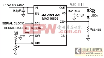
Figure 1. A 350mA linear HB LED driver IC such as the MAX16806 eliminates the need for a microcontroller or switch-mode converter.
Linear Driver Circuits Are Best for Interior Lighting
The best approach is to drive HB LEDs with a constant-current source. The simplest circuit to create a constant-current source is to have a MOSFET in series with an HB LED, measure the HB LED current, compare it to a reference voltage, and feed it back through an operational amplifier to control the gate of the MOSFET. This type of circuit behaves like an ideal current source, which keeps the current constant irrespective of forward-voltage and supply-voltage variations.Linear drivers are simpler to implement than switch-mode drivers, and linear drivers do not present EMI concerns since they do not employ high-frequency switching. Additionally, they minimize external component count, thereby reducing total solution cost.
Linear HB LED driver ICs such as the MAX16806, which integrates a MOSFET and a high-accuracy reference, provide brightness consistency between each light fixture (Figure 1). The MAX16806 requires an input supply that is only 1V above the total drop across the HB LED string. An external sense resistor measures the HB LED current, thus enabling the MAX16806 to keep the current constant when the input voltage or the HB LED forward-voltage changes.
The power dissipation in a linear driver is equal to the HB LED current times the voltage drop across the internal (or external) series pass device. As the HB LED current or input voltage increases, so does the power loss, thus limiting the use of linear drivers. Since overheating reduces HB LED lifespan—negating one of the key advantages of this light source—it is important to limit the power dissipation in the light fixture.
Fortunately, overheating can be avoided by momentarily dimming the HB LED. To accomplish this, the MAX16806 measures the input voltage; if the voltage exceeds its preprogrammed level, it will reduce the HB LED current, resulting in reduced power dissipation. This feature can eliminate the need for a switch-mode driver for applications such as automotive dome lights or DRL where the light can be dimmed in response to an abnormal high-battery-voltage condition.
Switch-Mode Step-Down Drivers Are Well Suited for Automotive Exterior Lighting
When the input voltage is higher than the total voltage across the HB LED string, it is best to use a switch-mode step-down (buck) converter driver (Figure 2), which minimizes the power dissipation and maximizes the driver efficiency in a light fixture.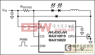
Figure 2. Using a switch-mode step-down converter driver minimizes the power dissipation and maximizes the driver efficiency in a light fixture.
Unlike the general-purpose buck controllers most commonly used to power HB LEDs, the MAX16819, MAX16820, MAX16822, and MAX16832 HB LED drivers employ hysteretic control. There is no control-loop compensation, which simplifies the design and further minimizes component count. An integrated high-voltage current-sense amplifier and up to 2MHz switching frequency reduce space and component count, making them ideal for front and rear automotive lighting (RCL, DRL, and fog/low-beam lights) applications.
Switch-Mode Buck-Boost (SEPIC) Drivers Are Ideal for Automotive Front Lights
When the input supply voltage varies above or below the total voltage across the HB LED string, a buck-boost driver topology should be used. In a buck-boost configuration, a floating current-sense amplifier is required to measure and regulate the HB LED current. Additional protection circuits are also required such as overvoltage protection in case the HB LEDs fail open or are shorted. The buck-boost circuit is ideal for driving high-power LEDs in automotive front-light applications where the input voltage can change from 5.5V for cold crank to 24V for double-battery conditions. The driver also needs to withstand over 40V load-dump spikes.Highly integrated HB LED drivers such as the MAX16812 or MAX16831 can help reduce component count and cost in front-light applications. The MAX16812, for example, integrates a floating differential current-sense amplifier and a 76V-rated, 0.2Ω power MOSFET designed to control the current in a single string of HB LEDs (Figure 3). Additionally, an internal dimming MOSFET driver enhances system reliability by automatically switching off power to the LED string during load-dump events.
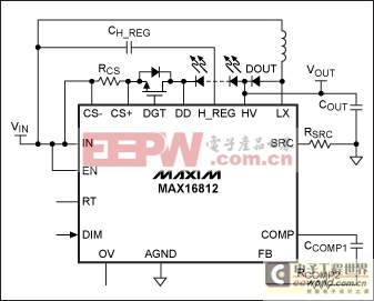
Figure 3. A buck-boost driver topology should be used in applications in which the input voltage varies above or below the total HB LED string voltage.
Switch-Mode Boost Drivers Enable LCD Backlighting in Automotive Designs
If the input voltage is always lower than the total voltage across the HB LED string, then a boost converter is necessary. This is common for applications such as heads-up displays or LCD backlights for 2010 and above model cars. These applications require a 3000:1 dimming range to accommodate the wide range of ambient light conditions encountered in automotive cabins. The driver must have an additional dimming MOSFET driver to be able to turn on/off the LEDs in a very short time. The dimming MOSFET can also protect the LEDs during load-dump conditions.Figure 4 presents a diagram for an HB LED driver designed for LCD backlighting in automotive applications. The MAX16834 integrates a high-side current-sense amplifier, a PWM dimming MOSFET driver, and robust protection circuitry to simplify the implementation of LCD backlighting applications. This HB LED driver offers a 3000:1 PWM dimming range, and features a 4.75V to 28V input operating-voltage range to ensure stable operation during cold-crank and load-dump events.
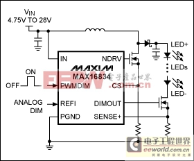
Figure 4. A boost driver with a wide, 3000:1 dimming range and built-in protection circuitry can be used for LCD backlighting in automotive infotainment applications.
Summary
Selecting the appropriate HB LED driver requires LED lighting system understanding to make the best tradeoffs. One needs to start with the basic electrical specifications such as input voltage, LED current, LED forward voltage, and their variations. The safety, EMI, thermal, and mechanical specifications as well as available board space must also be considered.Linear drivers should be used for low-cost, easy-to-implement, and low-EMI applications such as interior lighting. Switch-mode drivers are well suited for applications like exterior lighting that require high power, high efficiency, or a wide input operating-voltage range; however, they increase costs and may introduce EMI concerns.
Maxim has a wide portfolio of HB LED drivers specifically designed to reduce the size, complexity, and cost of solid-state lighting in automotive applications. All of our automotive lighting solutions are fully specified for -40°C to +125°C operation, and fulfill the general automotive requirements of short-circuit protection and thermal shutdown.




評論