電荷泵電壓分配器的性能-Properties of the
Though common in many of today's DC-DC energy converters, the charge-pump voltage converter is known mostly in its doubler and inverter configurations. This article focuses on the voltage-splitter configuration, which divides a given input voltage precisely by two. After a brief review of basic charge-pump principles, two applications will be covered: the efficient generation of a regulated 3.3V from two lithium cells and the efficient derivation of a 5V supply from 10V.
The Charge-Transfer Process
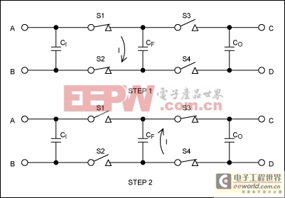
Just as magnetics-based converters employ inductors, charge-pump converters use a capacitor for storing and transferring energy. For the latest charge-pump converters, recent progress in semiconductor technology has exploded the 1MHz limit for working frequency. Higher frequency allows smaller components, and the simultaneous progress in multilayer ceramic capacitor (MLCC) technology has enabled the construction of converters that are small indeed. Their low component heights allow thin converters suitable for PCMCIA cards.Charge pumps have two basic topologies, doubler and inverter, both characterized by two steps of energy transfer (Figure 1). In each case the input capacitor (CI) ensures low impedance from the local source, which is therefore able to furnish high levels of transient current. To avoid voltage drops due to parasitic inductance, it is good practice to connect this capacitor very near the converter.

Figure 1. These bare-essential components illustrate the charge-transfer process.
CF is traditionally called the "flying capacitor." During Step 1, when switches S1 and S2 are closed and S3 and S4 are open, CF connects directly across the input voltage. The S1 to S4 switches should have very low series resistance. Charge then transfers between CI and CF until their voltages become equal in value and polarity. Because S1 and S2 are not ideal switches, the bulk of this charge transfer requires a finite amount of time for completion. After that interval, and provided that the input generator has very low source impedance, the voltage acquired by CF equals (almost) the input voltage VA - VB.
Step 2 consists of opening S1 and S2 while closing S3 and S4. For security, a delay is introduced between the two steps to avoid even a brief connection between the left and right parts of the converter. When S3 and S4 close, CF transfers charge with the output capacitor CO until these capacitor voltages reach the same value. Again, the duration of the exchange depends on the series resistance in S3 and S4. To avoid the effect of parasitic inductance, CF and CO should be connected very closely to the other components. Charge then transfers from CF to CO, provided that the output nodes are connected to a normal load (rather than to a generator).
Thus, CI transfers a finite amount of charge to CF, and then CF connects to CO. If Steps 1 and 2 are repeated a sufficient number of times (and if the output is not short-circuited), then the voltage across CO approaches that across CI. The circuit equalizes the differential voltages across the input and output nodes. This feature has enabled the construction of voltage generators with high-side drivers and a huge number of other applications, of which the voltage inverter and doubler are the simplest.
The inverter is obtained by connecting node C to node B, which usually becomes the ground reference. VA - VB = VC - VD, so if VB = VC = ground, then VD = -VA. Because nodes C and B are common, it is possible to fit this function plus a shutdown input in a 6-pin package. As an example, Maxim's MAX1697 charge-pump inverter delivers as much as 60mA of output current from a 6-pin SOT23 package.
The doubler is obtained by connecting node D to node A. VC - VA = VA - VB, so VC - VB = 2(VA - VB). If VB equals ground, then VC = 2VA. As an example among the wide family of Maxim? charge-pump doublers, the MAX1682 5-pin SOT23 device can generate twice the input voltage while supplying up to 45mA.
With proper connections, other devices can be configured in the inverter mode and the doubler mode as well. A MAX1681 in an 8-pin SO package, for example, can supply up to 125mA. The device operates with ceramic capacitors as small as 1μF, thanks to working frequencies that approach 1MHz.
Diverse technologies can be used to build the switches S1 to S4. Maxim parts employ true MOS switches, which allow current to pass in either direction when closed. This feature has interesting ramifications, because it allows energy transfer from output to input, as well as input to output.
The Voltage-Splitter Principle
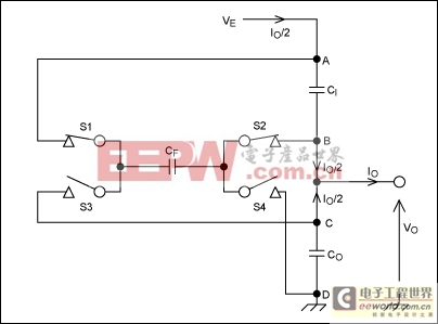
Each example above generates an output voltage that is double the input voltage. Another method, known for years, divides the input voltage by two (Figure 2). Labels and notation similar to those of Figure 1 show the analogies between this topology and that of Figure 1. This Figure 2 circuit can be considered an inverter, if B and C are treated as a virtual ground. (In that case, the negative output is node D.) The circuit can also be considered a doubler, if B and C are treated as the input and node A as the output.
Figure 2. The voltage-splitter topology can be regarded as an inverter or a doubler.
Either way, the charge pump tries constantly to maintain equal voltages across CI and CO, whether or not the capacitors differ greatly in value. If the charge pump had no internal loss and no output current, the identity between (VA - VB) and (VC - VD) would be exact. This property of charge-pump dividers (and multipliers) ensures a remarkably accurate voltage ratio without concern for component accuracy. One useful application is the generation of a negative voltage from its positive counterpart, without the loss of accuracy associated with an op amp and its resistor network.
Another useful property of this circuit is its very low output resistance. To evaluate this parameter, consider the definition of output resistance (RO) for a circuit such as the inverter of Figure 1. RO = [(VC-VD) open - (VC - VD)]/IO, where IO is the useful output current. In the inverter and doubler schemes, (VC-VD) open equals (VA - VB), because the input generator is supposed to have very low internal impedance. With regard to output current, (VA - VB) in those configurations does not change much.
This is not the case for the splitter configuration in Figure 2, in which the constant input voltage is (VA - VD). Every drop in output voltage (VC - VD) is compensated by an equal and opposite drop across (VA - VB). In that way the voltage splitter gains a factor of two in output resistance. Looking closely at the schematic, we see that the total current passing through the charge-pump regulator is not IO but IO/2, because at equilibrium no DC current can flow through CI, CF, or CO. Every charge received by CI during Step 1 is transferred to CO, with CF as the medium. The charge then transfers from CO to the output circuit. The charge delivered to CI by Ve continues through node B and joins the overall output current. At equilibrium, the charges and related currents are equal in value.
In perfect respect for the conservation-of-energy law, the input voltage sources IO/2 for an output current of IO. This again improves the output resistance by a factor of two, which means that the output resistance of a voltage splitter is one-fourth that of a doubler or inverter configuration. (The output resistance of a charge-pump inverter can be approximated as RO = TOSC/CF + 2RSW + 4ESRCF + ESRC0, where TOSC is the switching cycle time, RSW is the sum of the switch resistances, and ESRCF and ESRC0 are parasitic serial resistances of the flying and output capacitors, respectively.) This property is of great interest, because the voltage splitter has two-quadrants capability: It can transfer energy from output to input as well as input to output.
Making Good Use of Two Lithium-Ion (Li+) Cells in Series
To supply subsystems such as printing devices, some portable products require supply voltages greater than 7.5V. This requirement calls for high-amplitude short-duration current pulses, but not short enough for reliance on local reservoir capacitors. One solution is two Li+ cells in series, which provide 8.4V with low source impedance. The lower-voltage supplies usually required by the product's digital and analog sections can then be derived from 8.4V using linear regulators.Though simple, this approach is not very efficient. Printing operations are usually infrequent, yet 8.4V must be available continuously to supply the lower voltage rails. One simple and board-efficient way to overcome this problem is to use the circuit in Figure 3. IC1 is a 6-pin SOT23 inverter that supplies up to 60mA in the basic inverter mode, with a typical output impedance of 12Ω. The "U" suffix designates that the IC running at 250kHz requires capacitors no greater than 1μF and exhibits a typical output ripple of 30mVP-P for that condition.

Figure 3. This circuit splits the 8.4V battery voltage by two, and it derives 3.3V from 4.2V using an LDO linear regulator (IC2).
The "splitter-by-two" scheme confers a 120mA output-current capability, with much higher efficiency (83% typical) than that of a linear regulator (50% maximum for a 4.2V output). The more sensitive circuitry is supplied by the low-dropout (LDO) linear regulator IC2.Typical wideband RMS noise of IC2 is only 30μV, thanks to the 10nF capacitor C2. Energy transfer is obviously not reversible at this side of the circuit, because the LDO current can flow only from input to output.
The sum of the two output currents (not to exceed 120mA) is provided by the MAX1697U with typical output impedance of 3Ω. Low-ESR ceramic capacitors are recommended for best performance over the widest temperature range. Available in EIA-type CC0603 packages, these small capacitors are compatible in size with the two SOT23 packages.
A 250mA, Two-Quadrants Voltage Splitter
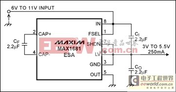
Video applications frequently require a 10V analog supply along with a 5V supply for digital and low-voltage analog circuitry. The charge-pump inverter in Figure 4 can deliver output currents as high as 125mA, with a low output impedance of 3.5Ω. The circuit also provides 5V by evenly splitting an input voltage of 10V to 11V.
Figure 4. A single IC delivers 250mA from an output voltage equal to half the input voltage.
Output impedance in the splitter scheme is no more than 0.9Ω, which represents a maximum drop of 225mV at full output current. The four high-power switches S1 to S4 reside in an 8-pin SO package that easily dissipates the 10% energy loss at full load. Today's 2.2μF ceramic capacitors fit in EIA CC0805 packages, and some are even smaller. A further increase in the capacitor values offers no major advantage beyond a reduction in output ripple.
This basic circuit is fully reversible, meaning that the output can sink current and send energy back to the input voltage. You can add LDO linear regulators in series with the 5.5V output to supply loads that cannot tolerate ripple. A p-channel LDO regulator such as the MAX603, whose maximum dropout is 220mV at 200mA, is well suited for this purpose.


評(píng)論