閱讀隔離數(shù)字國(guó)家的電力消耗-Read Isolated Di
Electronic systems must often isolate their inputs or outputs from the main reference common (ground). Various conditions can make necessary such galvanic isolation: the type of input sensor or driven actuator, safety considerations for medical equipment attached to a patient, or circuit components operating in an explosive or otherwise sensitive environment.
A requirement common to these applications is the need to sense the state of a digital line on the floating side of the circuit. That task is usually accomplished with an optocoupler, but optocouplers have limitations—they consume quite a bit of power from the sensing side, they are relatively slow, and the light emitter's aging reduces the current-transfer gain.
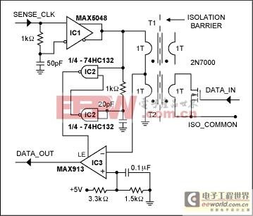
The circuit in Figure 1 replicates the state of a digital signal with no power drain from the side being sensed, and with only modest power consumption on the grounded side. It simply detects the value of a resistive load (the low RDSON of a fully conducting MOSFET, or an open circuit with the MOSFET off) applied to the secondary of a miniature, 1:1 single-turn transformer. Acquisition speed is a few tens of nanoseconds.

Figure 1. For each positive-going transition of SENSE_CLK, this circuit returns (at DATA_OUT) the state of the galvanically isolated digital signal at DATA_IN.
The front edge of the SENSE_CLK signal is differentiated by the combination of a MOSFET driver (IC1) and an RC circuit connected at its inputs. The differentiated 5V positive pulse from IC1 is then applied to a 2:1 inductive divider formed by the primaries of T1 and T2. The center point of this divider is connected to the inverting input of an ultra-fast comparator (IC3).
If the secondary of T2 is open (because DATA_IN = 0, thus turning the MOSFET off), the pulse amplitude is sufficient (about 2.5V) to force the comparator's internal output low. Meanwhile, the two gates of IC2 generate a short pulse (positioned in the middle of the pulse applied to T1 and T2), which is applied to IC3's latch enable (LE) input. LE latches the comparator's internal output to its external output (DATA_OUT), producing a low state that copies DATA_IN. However, if DATA_IN is high, the MOSFET is ON, which produces a low RDSON that reflects to the primary of T2. This reduces the pulse amplitude from the T1-T2 divider to a level no longer sufficient to trigger the comparator. The latching pulse at LE, therefore, forces DATA_OUT high, again copying the state of DATA_IN.
The ferrite core for T1 and T2 is a Fair-Rite? bead type (#2673000101), 3mm long and 3.3mm diameter, with a single turn for each primary and secondary winding. To minimize inductance, the connections between T2 and the MOSFET should be as short as possible. Breakdown voltage for the isolation barrier depends on the type of insulation used in the single-turn windings and in PC-board design and construction. Teflon? or Kapton? insulation, for example, allows a barrier voltage of several kilovolts. (The ferrite core is considered conductive.)
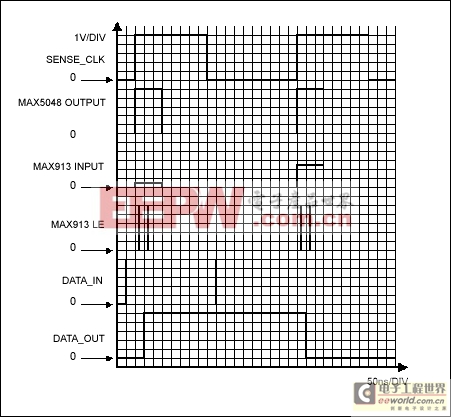
The I/O capacitance of the entire circuit, if carefully built, is determined by T2's interwinding capacitance. Using the core specified, plus 24-gauge wire with Teflon insulation, the resultant interwinding capacitance is less than 0.2pF. Acquisition delay from the positive edge of SENSE_CLK to DATA_OUT (Figure 2) is about 20ns.

Figure 2. Timing relationships for selected signals in the circuit of Figure 1.
A similar version of this article appeared in the November 25, 2004 issue of EDN magazine.


評(píng)論